CSC course, Espoo, Finland, 3-5 february 2004
David van der Spoel
|
GROMACS exercises CSC course, Espoo, Finland, 3-5 february 2004 David van der Spoel |
|
 |
|
|
|
|
| System |
Argon |
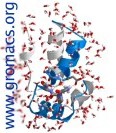
Water |
|---|---|---|
| Number of molecules |
216 |
216 |
| Box size |
6.0 (reduced units) |
1.86 nm |
| Temperature |
120 K |
300 K |
| Pressure |
1 bar |
1 bar |
| Main interactions |
Van der Waals |
Coulomb + Van der Waals |
| Features of the liquid |
Little structure |
Structured through hydrogen bonds |
| Potential/model used |
Van der Waals, reduced units |
Simple point charge |
|
|
|
|
|
|
|
|
|
|